A1601 settings: Difference between revisions
Telcredstaff (talk | contribs) |
Telcredstaff (talk | contribs) No edit summary |
||
| Line 3: | Line 3: | ||
==== With direct doors only ==== |
==== With direct doors only ==== |
||
The |
The A1601 controller can control one or two doors directly, meaning that the locks, monitors, and REX devices are connected to the physical connections on the controller. |
||
Latest revision as of 10:37, 26 January 2024
Door(s)
With direct doors only
The A1601 controller can control one or two doors directly, meaning that the locks, monitors, and REX devices are connected to the physical connections on the controller.
Select the first door from the dropdown list (you may need to create it first). If a second door should be controlled by this controller, select it from the second (optional) dropdown list.
With SimonsVoss SmartIntego
In combination with wireless locks from SimonsVoss SmartIntego, each controller can still manage one or two doors directly. In addition, a controller can manage up to 30 (recommended max value) wireless locks via one or more IP-connected hubs. One SmartIntego hub can manage maximum 16 doors and has a range of 20 - 30 meters.
The connection between the SmartIntego hub and the controller is done on the hub page.
With Assa Aperio
The Assa Aperio hub is connected physically to the reader socket on the A1001 and one controller can only manage one Assa Aperio hub. Hubs are available under the first dropdown list so select it here. Up to 8 Assa Aperio wireless locks can be managed by the hub.
In addition to the Assa Aperio hub, it is possible to let the controller manage one door directly. In this case, select it in the second (optional) dropdown list.
Lock settings
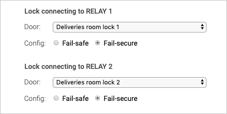
The A1601 controller has two relays that can be configured in the actual hardware (by moving a jumper) to deliver either a potential free contact, 12V or 24V when activated. These can be used in different configurations for a maximum of two doors, e.g.:
- One door with one 12V lock
- One door with two 12V locks
- Two doors with one 12V lock each
- One door with a 12V lock and second door with a lock controlled by a potential free contact
- etc.
For each relay that is used, it is necessary to specify which door it belongs to by using a dropdown list.
A common configuration is one door with two locks, where the second lock is locked during the night and unlocked during the day. For this configuration, the "night lock" should always be configured as "lock 2".
For relay that is used, it is also necessary to specify whether it should be configured as fail-safe or fail-secure:
- Fail-secure means that the door is locked if the power fails (it is secure from intruders on the outside). This is the default.
- Fail-safe means that the door is unlocked if the power fails (it is safe for people on the inside, e.g. in the event of a fire).
NOTE: In order for fail-secure and fail-safe to work as intended it is important to connect the wires from the lock to the relay in the correct way. Minus (-) from the lock should be connected to minus (-) on the controller and plus (+) from the lock should be connected to NO on the controller.
Monitor settings
For each door that is attached to this controller, a door monitor can be used. A common type of door monitor is a magnet sensor. The door monitor senses if the door is open or closed and has two purposes:
- A door open too long alert will be generated if the door is open too long (configurable for each door).
- A "door forced open" alert will be generated if the door is opened without a prior access granted event, such as presenting a valid credential to the reader or using the REX button (see below).
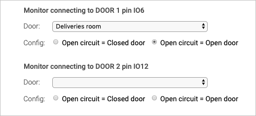
There are two monitor inputs; one on socket DOOR 1 pin IO6 and one on DOOR 2 pin IO12.
Make the connection between monitor input and door by using the dropdown list. Also specify if an open circuit means that the door is open or closed. The default is open circuit = open door.
Reader settings
Maximum two readers can be attached to the A1601 controller (or one if a hub is used). Possible combinations include:
- One door and one reader
- Two doors and one reader each
- One door with two readers (one for each direction)
- No readers at all (if only credentials of type Remote are used)
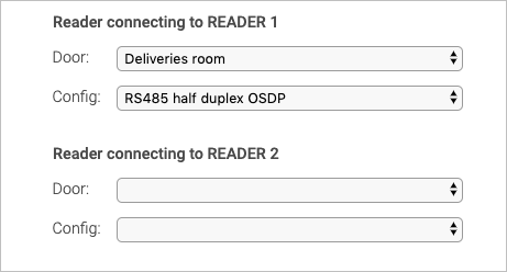
Make the connection between reader socket and door by using the dropdown list.
Also specify the type of reader. Supported reader types are:
- RS485 half duplex OSDP
- Wiegand single LED
- Wiegand double LED
REX settings
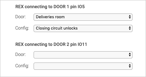
REX (Request to EXit) devices are inputs that trigger by either opening or closing a circuit. A typical REX device is an "open button" that unlocks (or more exactly; grants access to) the door from the inside. Maximum two REX devices can be attached to an A1001 controller.
Make the connection between REX device and door by using the dropdown list and specify whether opening or closing the circuit should trigger the request to exit.
A special case of using a REX device / input is where a user opens the door manually and the door has a door monitor. Normally, this will trigger the door forced open alert, but this may not be the desired behavior. In this case, it is possible to use a specific REX device that will trigger as soon as the door starts to open and configure it as either Closing circuit allows or Opening circuit allows. The effect of this is to prevent the door forced open alert to be generated.
IO port settings
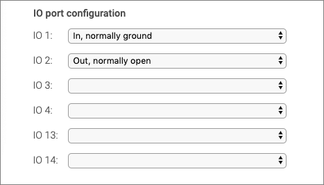
The A1601 Network door controller has six configurable IO ports. These ports can be used with Commands and triggers; an input port can act as a trigger, and a command can activate an output port. In order to use the IO ports, they first need to be configured.
Each IO port can be configured either as input or output. It is also necessary to define what the normal state of the port is: ground or open. For more information on the use of IO ports, see the section on Commands and triggers.
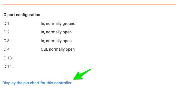
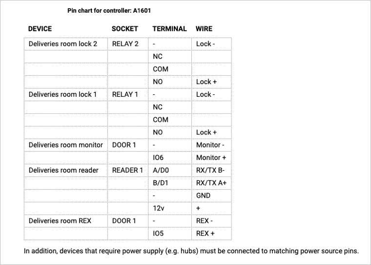
Pin chart
After saving or editing the settings for an A1601 controller, Telcred Access Manager can generate a pin chart that summarizes the physical connections on the controller. The pin chart is accessed by clicking the link at the bottom of the controller detail screen:

