A1001 settings
The Axis A1001 Network Door Controller can control one or two doors with electric locks and up to eight Assa Aperio locks via a connected Aperio hub. There are quite a few settings for a controller and they are all explained on this page.
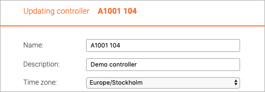
Name, description and time zone
It is mandatory to give the controller a name and it is optional to give it a description.
The time zone of the controller will default to the time zone of the organization but can be changed.
Connection settings
There are two ways that a controller can connect to the Telcred service: O3C and Direct. O3C stands for One-Click-Connection-Component and is a technology developed by Axis Communications. It is the default and recommended way to connect a controller, since it is both simpler and more secure than Direct.
O3C
With O3C, it is always the controller that initiates the communication with the Telcred service. The connection is encrypted with HTTPS and since most routers and firewalls allow outgoing HTTPS traffic, there is no need to configure port forwarding or open up the firewall.
In order to use O3C, it is necessary to know the MAC address of the controller (printed on the controller label as S/N) and something called OAK (Owner Authentication Key). The OAK is printed on a sticker that is included in the packaging for a new A1001 controller. If it has been lost it is possible to retrieve it by asking Axis or Telcred (in which case you need the MAC address.
Directly after saving the configuration for a new controller with O3C, the Telcred service uses the MAC and OAK to connect to a Dispatch server which is maintained by Axis communications and "claim" this controller. If this process is successful, the controller connection status will change to Ready to connect in the Telcred system.
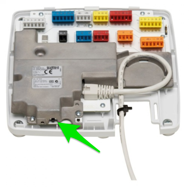
At this stage, it is necessary to press the control button on the A1001 for 1-2 seconds.
Pressing the control button will cause the A1001 to connect to the Axis Dispatch server and download a small certificate with all the information it needs to connect to the Telcred server in a secure way. This should happen a few seconds later and when it has successfully established a connection to Telcred Access Manager, its connection status will change to Online.
From this point on, the controller will always try to connect to the Telcred service after it has been offline - even if it is moved to a different network.
Direct
With Direct communication it is the Telcred service that initiates the communication with the controller. The connection is encrypted (HTTPS), but in most cases port forwarding needs to be configured in the router and the firewall may need to be opened up.
The only information necessary for direct connection is the IP address and port number on which the Telcred service should contact the controller. Obviously, it needs to be the external IP address since the connection is initiated outside the network on which the controller sits.
Internal IP and Firmware version
In view mode, the internal IP address, i.e. the address on the local network, is displayed. This is only for information and the IP address cannot be changed through Telcred Access Manager.
The firmware version is also displayed, and in edit mode it is possible to update the firmware.
Door hub
If the controller will be used to control Assa Aperio locks, the setting Use a door hub must be set to yes. The default is no.
If set to yes, the door hub can be selected in a drop down list (of course, you may need to create the door hub first - see further the page about Assa Aperio).
If an Assa Aperio door hub should be used, it must always be connected to the READER DATA 2 socket, and more specifically pin 3 and 4.
Door(s)
The A1001 controller can control one or two doors directly (or one door directly and up to eight Assa Aperio doors via a door hub).
Select the first door from the dropdown list (you may need to create it first). If a second door should be controlled by this controller, select it from the second (optional) dropdown list.
Lock settings
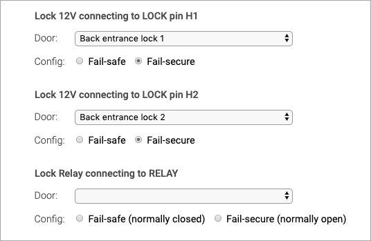
The A1001 controller has three lock outputs; two that deliver 12V on/off and one relay. These can be used in different configurations for a maximum of two doors, e.g.:
- One door with one 12V lock
- One door with two 12V locks
- Two doors with one 12V lock each
- One door with a 12V lock and second door with a relay controlled lock
- etc.
For each lock output that is used, it is necessary to specify which door it belongs to by using a dropdown list.
A common configuration is one door with two locks, where the second lock is locked during the night and unlocked during the day. For this configuration, the "night lock" should always be configured as "lock 2".
For each lock output that is used, it is also necessary to specify whether it should be configured as fail-safe or fail-secure:
- Fail-secure means that the door is locked if the power fails (it is secure from intruders on the outside). This is the default.
- Fail-safe means that the door is unlocked if the power fails (it is safe for people on the inside, e.g. in the event of a fire).
Monitor settings
For each door that is attached to this controller, a door monitor can be used. A common type of door monitor is a magnet sensor. The door monitor senses if the door is open or closed and has two purposes:
- A door open too long alert will be generated if the door is open too long (configurable for each door).
- A "door forced open" alert will be generated if the door is opened without a prior access granted event, such as presenting a valid credential to the reader or using the REX button (see below).
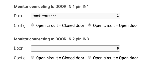
There are two monitor inputs; one on socket DOOR IN 1 and one on DOOR IN 2.
Make the connection between monitor input and door by using the dropdown list. Also specify if an open circuit means that the door is open or closed. The default is open circuit = open door.
Reader settings
Maximum two readers can be attached to the A1001 controller (or one if a hub is used). Possible combinations include:
- One door and one reader
- Two doors and one reader each
- One door with two readers (one for each direction)
- No readers at all (if only credentials of type Remote are used)
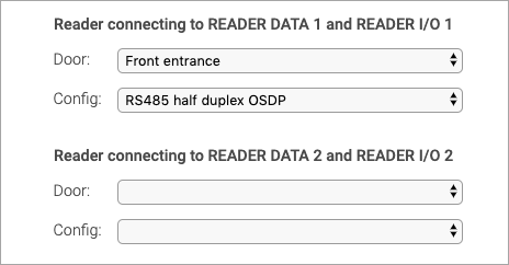
Make the connection between reader socket and door by using the dropdown list.
Also specify the type of reader. Supported reader types are:
- RS485 half duplex OSDP
- Wiegand single LED
- Wiegand double LED
REX settings
Maximum two REX (Request to EXit) devices can be attached to an A1001 controller. A typical REX device is an "open button" that unlocks the door from the inside (or more exactly, grants access). The purpose of using a REX device is typically one or more of the following:
- Unlock the lock(s) for a few seconds (grant access)
- Trigger a door opening mechanism
- Prevent the door forced open alert if a monitor is used
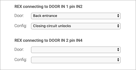
REX devices are inputs that trigger by either opening or closing a circuit. Make the connection between REX device and door by using the dropdown list and specify whether opening or closing the circuit should trigger the request to exit.
A special case of using a REX device / input is where a user opens the door manually and the door has a door monitor. Normally, this will trigger the door forced open alert, but this may not be the desired behavior. In this case, it is possible to use a specific REX device that will trigger as soon as the door starts to open and configure it as either Closing circuit allows or Opening circuit allows. The effect of this is to prevent the door forced open alert to be generated.
Pin chart
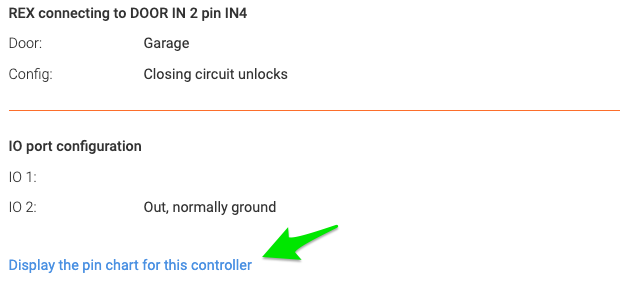
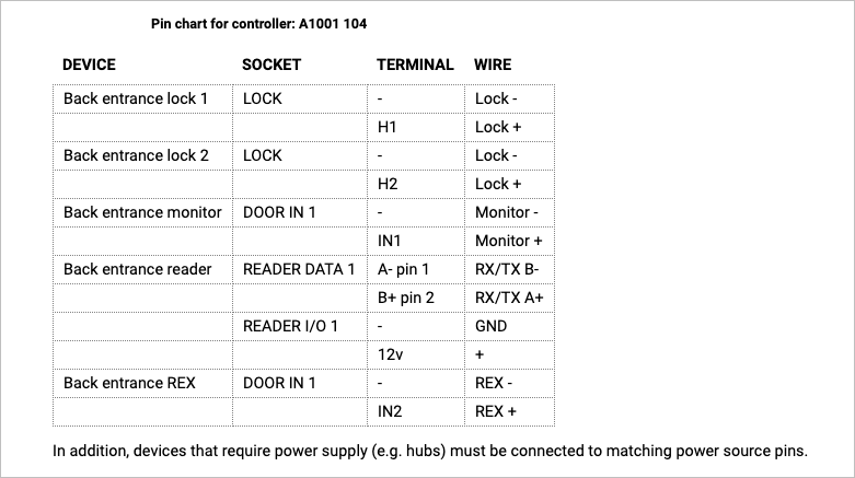
After saving or editing the settings for an A1001 controller, Telcred Access Manager can generate a pin chart that shows to to do the physical connections on the controller. The pin chart is accessed by clicking the link in the lower right hand corner of the controller detail screen:
